Creating a Sine Wave Function Generator with Mercury 2
What is a function generator?
Function generators play a huge role in electronics. Very simply, a function generator is a piece of equipment used to produce sine, triangular, sawtooth, and square electrical waves over a wide range of frequencies (typically less than 20 MHz). They are primarily used for the development, testing, and repair of electronics. The sine wave in particular is important for use in analog circuit development.
What’s so important about a sine wave?
Creating the sine wave function generator is just the beginning. Starting with this technology, we could expand it into Digital Signal Processing, creating sound mixers, producing signals, phase locked-loops, and oscillators used in wireless communications, etc… There are many possibilities and it starts out with creating a variable frequency sine wave.
What will I need to create a sine wave function generator?
Using the VHDL modules included below, you can create your own sine wave function generator by:
Using the Mercury 2’s on-board 10-bit Digital-to-Analog Converter (DAC) to produce the amplitude of the sine wave.
Implementing a Serial Peripheral Interface (SPI) system to provide the 10-bit phase amplitude to the DAC.
Utilizing a pipe-lined Coordinate Rotation Digital Computer (CORDIC) to calculate phase amplitude.
Implementing a simple phase accumulator to provide the phase to the CORDIC.
Defining the frequency of your sine wave (47.5 Hz to 100 kHz) by using the 5V tolerant I/O on the Mercury 2 development board.
As you can see, there are quite a few modules that provide some powerful tools to you in implementing your sine wave generator. Descriptions of how each of these modules work is provided, but is not necessary for you to start creating your own function generator now. It will also be noted that all of these modules are created with the Mercury 2’s development board in mind, however, some of the entities provided here can be implemented on any FPGA such as the CORDIC or SPI communication modules.
Download the files for the Sine Wave Generator!
Go ahead and click the button below to download the .zip file and unzip the VHDL files where you want to create your project. We will be using these as source files for our Vivado 2018.2 project.
Create a new project
If you are fairly new to using Vivado 2018.2, check out our tutorial on creating a new project by following the steps outlined in our Getting Started with Mercury 2 page. Once you are familiar with how to create a new project from scratch, we can adapt this knowledge to create a project from the existing VHDL files for the sine wave generator.
Creating a project with source files
We will deviate from the tutorial first by ensuring that the “Do not specify sources at this time” box is left unchecked. This will allow us to specify the VHDL files to be added to the project before it is created. After unchecking the box, click next to add the source files.

Source files are added by clicking the “Add Files” button navigating the explorer to where you unzipped the files for the Sine Wave Generator and selecting all the VHDL files. Then click “Ok” to complete the addition of the source files into your project.


Once you click “Next”, follow the rest of the instructions for creating the project as found in the Getting Started with Mercury 2 tutorial including selecting the device and adding the Xilinix Design Constraints (XDC file) to your project.
Structure of the Sine Wave Generator
The structure of the sine wave generator is made up of many different components that do their individual and specific task. These components are called modules that consist of two parts - the entity and the architecture.
The entity is the part of the module that is used to communicate with other modules through their entities or to the FPGA by mapping to a pin that is specified in the Xilinx Design Constraint (XDC). The architecture of the module is what designates how the module will work given the parameters passed through its entity.
With the sine wave generator, the hierarchy of modules are shown in the diagram below.
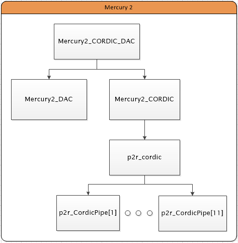
You will note that all the modules are required to create the sine wave generator. The structuring of the project is done automatically in Vivado when the project is created. You can verify the hierarchy of the structure by expanding the “Design Sources” folder in the “Sources” window. Each level is illustrated by indenting sub-modules to the right.

Create Sine Wave Generator with Mercury 2
After module hierarchy is verified, you can now continue with the generation of the .bit file for the project and then burning it onto the flash memory of the Mercury 2 board. For help in carrying out these steps, refer to the getting started with Mercury 2 guide.
Now comes the fun part - running the sine wave generator and experimenting with it. The output of the sine wave generator immediately starts creating a sine wave when the power to the Mercury 2 board is connected. Play around with the 5V tolerant I/O inputs 0 through 7 to see how your sine wave changes! The output frequency will be the base frequency of the sine wave generator multiplied by the unsigned binary value inputted to I/O inputs 0 through 7 with input[0] being the least significant bit (LSB) and input[7] being the most significant bit (MSB).