Getting Started with Mercury 2
Let's get started with Mercury 2! This simple tutorial will demonstrate how to take your design written in VHDL, compile and synthesize it using Xilinx Vivado 2018.2, then program the bitstream via USB to embed your Mercury 2 device with your program!
We will cover a few important details throughout this tutorial. While there are steps that are specific for use on the Mercury 2, the concepts are general for use in all embedded systems applications whether you’re a fan of Xilinx products or you use other like products. The steps for creating a working project will be the same, but will require a different platform such as Quartus II for Altera products. Here’s what you can expect to learn from following the steps in this tutorial:
How to create a new project using Xilinx Vivado 2018.2.
Selecting the appropriate device to run your project (Artix 7 FTG256 in our case).
Create new source files (VHD file) to be used in your project.
Add design constraints (XDC file) so your device knows how to process the inputs and outputs in your source file.
Compile and implement your project according to your device and the constraints given.
Create a bitstream (BIT file) that will be downloaded into the flash memory on your device.
Program the Mercury 2 board by using our programmer GUI.
We hope you will have fun in starting your work and will continue to explore the amazing possibilities available with micro-controllers.
Step 1: Download and install the design tools
Xilinx offers a free FPGA design suite called Vivado WebPACK that can be accessed after creating a free account with Xilinx.
Create a free account: https://www.xilinx.com/registration/create-account.html
For the Artix-7 you must use Vivado 2018.2:
https://www.xilinx.com/support/download/index.html/content/xilinx/en/downloadNav/vivado-design-tools/archive.html
NOTE: You must install Xilinx Vivado 2018.2 to support the Artix-7.
The Mercury Programmer burns a bitstream to the flash chip on the Mercury board.
It is available for download here:
Step 2: Create a Xilinx Vivado project
After installing Vivado 2018.2, launch the Project Navigator. This is found in:
Start > Xilinx Design Tools > Vivado 2018.2
From the "File" menu, select Project > New
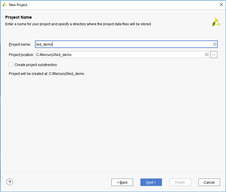
After starting the project wizard by clicking “Next” enter in the project name and file location as shown.
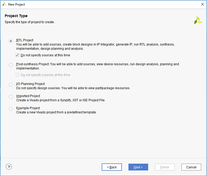
After pressing "Next", determine the project type. For this project, select “RTL” as the project type. Since this is our first project, also select the “Do not specify sources at this time” checkbox.
Note: In the future, project source files and user constraint files can be added to the project prior to creation by ensuring the “Do not specify sources at this time” checkbox is left unchecked and then following the project wizard through the addition of source and constraint files.
After pressing “Next” we are presented with a list of devices that our project will be implemented on. Select the specific device (XC7A35TFTG256-1) by scrolling through the list or by entering the device into the search bar or entering the appropriate information into the filter tools. Click on the desired device and then click “Next”.

After clicking "Next", we are asked to confirm our project settings.

After clicking "Finish", we are greeted with a fresh, new project window!

Step 3: Add the Mercury Xilinx Design Constraint file
Next, we must add a Xilinx Design Constraint file (XDC). This is very important; it is here that we specify:
Pin name and corresponding location
Pin voltage standard (LVTTL, LVCMOS, etc)
Timing constraints (clock period and duty cycle)
Below is an excerpt from the Mercury XDC file, dealing with the clock and three LEDs. The physical pin location for each of these signals is specified along with their voltage standard. For example, check the schematic, and one would see that pin N14 on the FPGA is connected to the 50MHz oscillator and that the voltage standard is LVCMOS 3.3V.
# on-board system oscillator
set_property -dict {PACKAGE_PIN N14 IOSTANDARD LVCMOS33} [get_ports {clk}]

# on-board user LEDs
set_property -dict {PACKAGE_PIN M1 IOSTANDARD LVCMOS33}  [get_ports {led[0]}]
set_property -dict {PACKAGE_PIN A14 IOSTANDARD LVCMOS33} [get_ports {led[1]}]
set_property -dict {PACKAGE_PIN A13 IOSTANDARD LVCMOS33} [get_ports {led[2]}]
The complete User Constraint File can be downloaded for the Mercury 2 board by clicking on the button below to download the file.
After downloading the XDC, unzip it, then add it to the project by right-clicking the “Constraints” folder from the hierarchy section of the Sources window and selecting “Edit Constraints Sets…”.

Next click on the “Add Files” and navigate the file explorer to the UCF that you downloaded. Once the file is added to the project constraints, click “OK”.

The XDC is now added to your project! You can verify the addition of the file by checking the Constraints folder in the Sources window for Mercury2.xdc.

Step 4: Write some VHDL code!
Let's create a VHDL file and make a simple design. Right-click the “Design Sources” folder from the hierarchy section of the Sources window and select “Add Sources..”.

From the “Add Sources” wizard, select the “Add or create design sources” from the radio button choices then click “Next”.

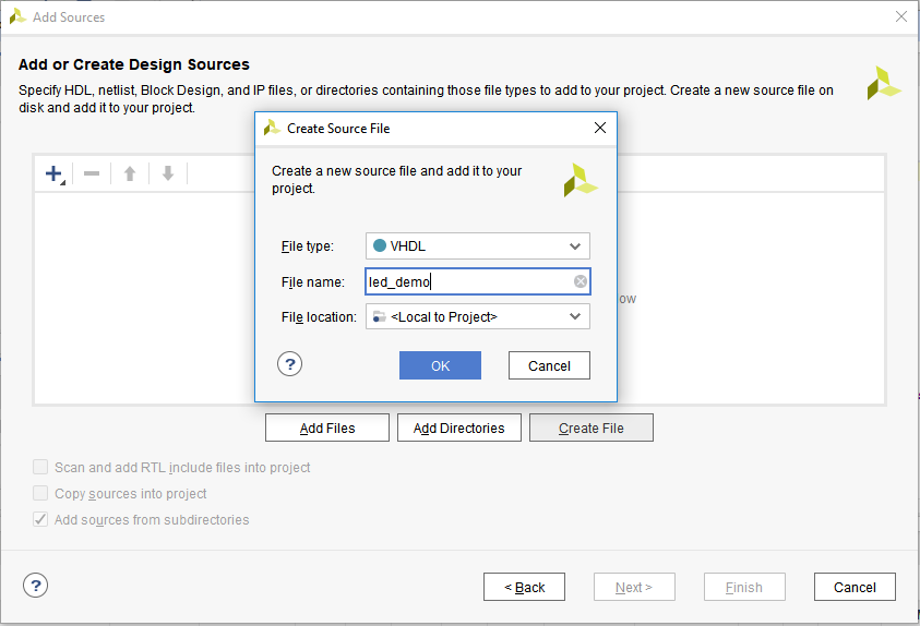
Create a new source file by clicking on the “Create File” button. Specify file type as VHDL and name the file the same as the project. In this case, the file name will be “led_demo”. Finish the creation of the source file by specifying file location as “Local to Project” and click “OK”.
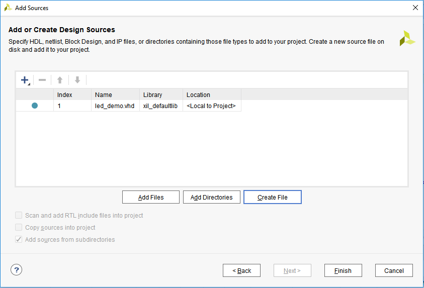
Complete the addition of the VHDL source file by clicking the “Finish” button.
Optional: Input and Output ports can be added to the source VHDL file by defining them as shown in the image below. Inputs and Outputs can also be hard coded in the VHDL file later.

You can verify the addition of the source VHDL file by checking the “Design Sources” folder in the Sources window.
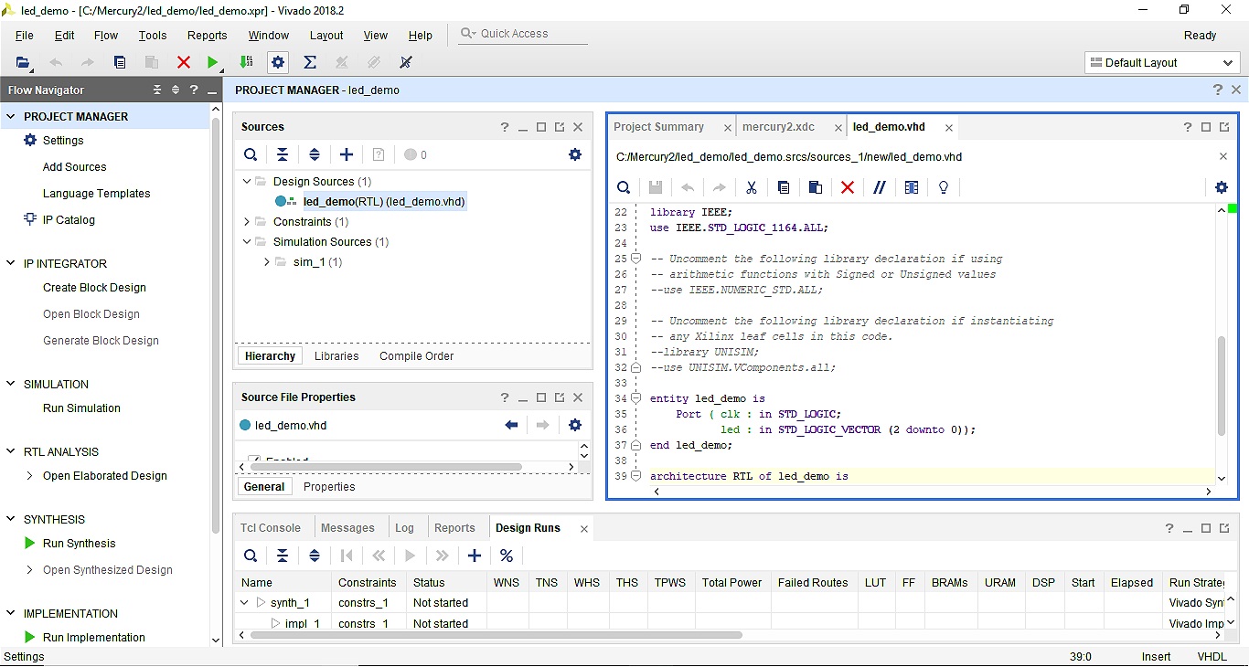
Let's go ahead and code a simple example that flashes the LEDs on and off, with a period of one second.
library IEEE;
use IEEE.STD_LOGIC_1164.ALL;

entity led_demo is
  port
    (
      clk : in std_logic;
      led : out std_logic_vector(2 downto 0)
    );
end led_demo;

architecture RTL of led_demo is

  signal count : integer range 0 to 49999999 := 0;
  signal pulse : std_logic := '0';

begin

  counter : process(clk)
  begin
    if clk'event and clk = '1' then
      if count = 49999999 then
        count <= 0;
        pulse <= not pulse;
      else
        count <= count + 1;
      end if;
    end if;
  end process;

  led(2 downto 0) <= (others => pulse);

end RTL;
We want to flash an LED: on for 1 second, then off for 1 second.
To achieve this, we have written a "counter" process (that runs on the 50MHz clock) and counts from 0 to 49,999,999. After reaching the maximum value, it resets "count" register to zero, and flips the state of "pulse" register. All three LEDs have been wired to "pulse".
Step 5: Compile our design!
Let's go ahead and compile our design.
The Mercury 2 programmer requires a .bit file of the synthesized and implemented design of our project in order to run. All three processes can be done by clicking the “Generate Bitstream” option from the Flow Navigator window in Vivado. This will initiate design synthesis, implementation, and generate the bitstream for the project. The "Synthesize" process takes the hardware described in VHDL, and infers the logical building blocks (registers, state machines, adders, etc.) that were described. The "Implement" process takes this design and tries to implement it using the resources available on the FPGA.

Step 6: Program the Mercury board
Now, let's program the Mercury 2 board with the bitstream we just generated! The files for the Mercury 2 Programmer can be found by navigating here. The steps hereafter will illustrate how to program your Mercury 2 board using the Windows command line application wrapper (mercury2_progGUI-windows.exe).
Note: For ease of use, keep both the command line application (mercury2_prog.exe) and the command line application wrapper for windows (mercury2_progGUI-windows.exe) in the same folder.
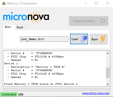
First, open the Mercury 2 Programmer GUI. Make sure your Mercury 2 device is connected to your computer via the USB port. Connect to your device by clicking on the “Connect Device” button in the upper right hand corner of the window.

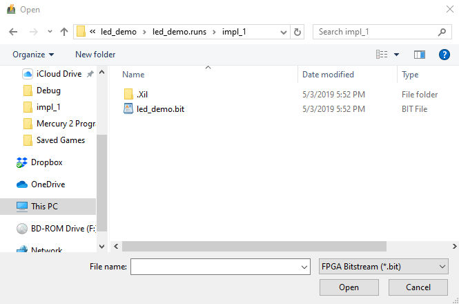
Next, navigate to your bit file location by clicking on the “Load”. In this case, our bit file is found at Mercury2 > led_demo > led_demo.runs > impl_1 > led_demo.bit
We will be using this bit file with the programmer to burn our design onto the flash chip used on the Mercury 2 board.
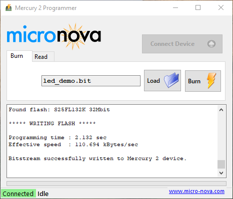
Then click "Burn" to write this file to the FPGA.
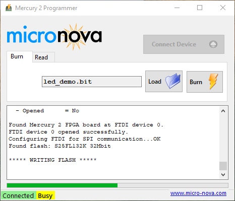
The progress bar will scroll by as the flash chip is being written to. This process should take about 10 seconds.
The flash chip on the board has been programmed, and the FPGA will immediately boot using the newly programmed bitstream. (Since this is stored on flash, the bitstream is non-volatile.)
The LEDs on the Mercury 2 board will now be flashing.

We are now up and running with Mercury 2!